

Corliss Engine Review TRIAD Advantages
Another simple process that TRIAD utilizes in its boiler operations is that of sequencing. Knowing what it is and how it works allows users to fully maximize their equipment’s use and economic life.
TRIAD Boilers can be sequenced through the use of control panels, allowing users to enjoy many benefits, including:
- Temperature set-back during reduced-heat requirement, especially at night or during weekends.
- Adjustments for latent heat to make full use of hot boiler-water that retains heat after the burner has shut down.
- Outdoor reset based on atmospheric temperatures.
- Monitoring of return-water temperatures to maintain accurate heating output.
This process of sequencing can also be easily applied in our boilers that use the control panels of any other major boiler manufacturer.
All TRIAD hot-water and steam boilers are completely-assembled, packaged-products, which offer several advantages over boilers that need to be installed at the jobsite. Obviously, there are several advantages to this TRIAD feature, namely:
- On-site installation labor costs are reduced.
- Greater and more consistent quality control is achieved at the factory than onsite.
- The facility of installation of modular boilers leads to faster start-up.
TRIAD boilers are easy to clean.
To maintain boiler efficiency and longer boiler life, heating surfaces must be kept clean at all times. All TRIAD heating surfaces, especially the fire-tubes, are easily accessible. On the other hand, it is almost impossible to clean all the heating surfaces of cast-iron boilers and even parts which are accessible are quite difficult to clean.
TRIAD boilers also allow easy cleaning of water surfaces. However, cleaning the interior of a cast-iron boiler is a big challenge and may only include cleaning the vertical surfaces which can greatly affect operating efficiency.
A clean machine is a joy and pride to its user. TRIAD understands this truth perfectly and works to make it a reality.
TRIAD boilers are easy to repair.
Owing to their steel construction, TRIAD hot-water and steam boilers can be repaired in the job-site with little inconvenience to operations. Any leak can be permanently welded or the tubes re-rolled easily. Everyone knows how hard it is to permanently weld a cracked cast-iron boiler section or a leaking, copper-fin-tube boiler. The fire-tubes are easily reachable through the top and through the fire-door in TRIAD boilers.
These many advantages make TRIAD Boilers worth having and using for many years in various applications.
Contact us today to find out more how you can avail of these benefits.
1099 Atlantic Drive, Unit 2
West Chicago, IL 60185
Phone: (888) 526-5245
Fax: (630) 562-2800

Corliss Steam Engine Boiler Group Gear Rooms Smelter Tech: The Corliss Engine
While James Watt’s improvements to the steam engine may have been responsible for giving birth to the industrial revolution it would be the contribution of George Corliss that made it profitable. Watt’s contribution to engine design was one of practicality and reliability. Corliss’s contribution was one of efficiency, creating engines that took advantage of every last drop of energy available to it. Because of these improvements steam engines were finally able to surpass water power in terms of economic feasibility and surge ahead to become the de factor power source of the late 19th century.
On its surface the Corliss styled engine is very similar to its Watt’s style brethren. Steam is delivered into a large cylinder through means of a throttle valve, which is automatically controlled by the engine’s governor. Once inside the cylinder that steam expands and pushes the enclosed piston forward. As the piston moves so to does the connected piston rod, which in turns pushes the crosshead forward along its track.
Meanwhile on the engine’s business end that reciprocating motion of the crosshead is converted into circular motion by means of a connecting rod and crank. The crank rotates a disc which in turn spins the engines drive shaft and connected flywheel. This is all typical when it comes to steam engine design (see my original steam engine post HERE for more info). To see what differentiates this Corliss engine from other steam engines of the period you have to look inside the cylinder itself…
Corliss Steam Engine Boiler Group Gear Rooms Smelter Tech: The Corliss Engine
Related Articles:
http://jonaskosovo.quora.com/Corliss-Boiler-Room-Steam-Engine-Group-by-George-H-Corliss
http://en.wikipedia.org/wiki/History_of_the_steam_engine
http://www.newsm.org/steam-engines/steam.html
http://www.albert-gieseler.de/dampf_de/firmen0/firmadet866.shtml
http://www.coppercountryexplorer.com/2009/12/smelter-tech-the-corliss-engine/
Corliss motor gruppe Gear mekanismer: Corliss motor mekanismer
Corliss motorer har fire ventiler for hver sylinder, med damp og eksos ventiler på hver ende. Corliss motorer innlemme forskjellige forbedringer i begge ventilene seg og ventil utstyret, at systemet sammenhengene som opererer ventilene.
Bruk av separate ventiler for opptak og eksos betyr at ventilene verken steam passasjer mellom sylindere og ventiler må endre temperaturen under makt og eksos syklus, og det betyr at tidspunktet for opptak og eksos ventiler kan styres uavhengig. Derimot har konvensjonelle dampmaskiner skyveventil eller stempelet ventil som vekselvis feeds og eksos gjennom passasjer i hver ende av sylinderen. Disse passasjene er utsatt for bredt klimasoner under denne operasjonen, og det er høy temperatur graderinger i ventil mekanisme selv.
Clark (1891) kommenterte at Corliss utstyret er en kombinasjon av elementer tidligere kjent og brukt separat, påvirker sylinderen og ventil-utstyr'.Opprinnelsen til Corliss utstyret med hensyn til tidligere steam valve utstyr ble sporet av Inglis (1868).
George Corliss fikk oss Patent 6162 for hans ventil utstyr på 10 mars 1849. Dette patentet dekket bruk av et håndledd-plate å formidle ventil bevegelse fra en enkelt eksentrisk fire ventiler av motoren, og det dekket bruk av turen ventiler med variabel cutoff guvernør kontroll som karakteriserer Corliss Engines.Unlike senere motorer, hvorav de fleste var vannrett, dette patentet beskriver en loddrett bjelke motor og det brukes personlige lysbildet ventiler for opptak og eksos i hver ende av sylinderen.
Vik ventilene trekkes åpen med en eksentrisk-drevet pawl; Når pawl turer, rask nedleggelse er dempet med en dashpot. I mange motorer, det samme dashpot fungerer som en vakuum våren å trekke ventilene lukket, men Corlisss tidlige motorene var treg nok til at det var vekten av dashpot stempelet og stangen som lukket ventilen.
Hastigheten på en Corliss motor kontrollert av varierende cut-off av damp under hvert strøk, mens gass åpen tiden hele. Dette er sentrifugal guvernøren knyttet til et par kameraer, ett for hver opptak ventil. Disse cams finne punktet under stempelet slag som på låsen release, tillater at ventilen lukkes.
Som med alle dampmaskiner der cut-off kan reguleres, er i kraft av gjør så ligger i faktum at de fleste av streken drevet av damp i sylinderen etter opptak ventilen er stengt. Dette kommer langt nærmere den ideelle Carnot syklusen som er mulig med en motor der opptak ventilen er åpen for lengden av streken og hastigheten er regulert av en Gasspjeld.
Corliss ventil giret tillatt mer ensartet fart og bedre respons laste endringer, slik at det passer for programmer som valseverk og spinning, og i stor grad utvide sin bruk i produksjon.
Corliss ventilene åpne direkte inn i sylinderen. Ventilene koble sylinderen for å skille steam og eksos plenums. I utgangspunktet Corliss brukt lysbildet ventiler med lineære aktuatorer, men av 1851 Corliss hadde flyttet til semi roterende Ventilaktuatorer, som dokumentert i US Patent 8253. Denne motoren, ble håndleddet platen flyttet til midten av siden sylinder på senere Corliss motorer. Dette var en bjelke motor, men og semi roterende Ventilaktuatorer drives lysbildet ventiler i fire ventil kistene av motoren.
Corliss ventilene er i form av en liten sirkulær segment, roterende inne en sylindrisk ventil-face. Deres ventilen mekanismen er av langs aksen av ventilen, dermed de har lite "dead space" som stammen av en poppet ventil og hele havneområdet kan brukes effektivt for gasstrømmen.
Som en Corliss ventil er liten i forhold til havneområdet, generere effekten av gasstrømmen relativt liten dreiemoment på ventilen akselen sammenlignet med noen andre slags ventil. Disse fordelene har ført til Corliss form av ventil som brukes i andre roller, fra dampmaskiner med Corliss utstyr.
Rolls-Royce Merlin aero-motoren brukte en rektangulær spjeldventil som en gass. Gass-flow styrker handler asymmetrisk på denne sommerfugl kan føre til dårlig kontroll av makt i noen tilfeller. Sen modeller, fra 134, brukes en Corliss Gasspjeld i stedet å unngå dette problemet.
Et felles trekk ved store Corliss motorer er ett eller to sett med smale tannhjulet i kanten av svinghjulet.[10] Disse tennene tillate svinghjulet å bli utestengt, altså slått ved hjelp av et kubein. Dette kan være nødvendig under motorvedlikehold, for eksempel å angi cut-off og opptak ventilinnstilling, og det kan være nødvendig under motoren starter.
Behovet for sperring motoren under Start er mest åpenbart på én-sylindret motorer, der en uforsiktig motor operatør kan stoppe motoren med stempelet i eller nær dødt sentrum. Når stoppet i denne tilstanden, kan ikke motoren startes under sin egen makt, så det må bli utestengt til en mer gunstig posisjon for å starte.
Store Corliss motorer kan ikke trygt starte kaldt, slik det er vanlig å innrømme lavt trykk damp til begge sider av sylinderen å varme opp metallarbeider. Snu motoren sakte i løpet av denne prosessen sikrer at hele motoren varmes jevnt, og det sikrer at olje er fordelt gjennom mekanisme før makt. Igjen, sperring kan brukes til å gjøre dette, selv om operatører noen ganger gjør dette ved forsiktig manuell manipulasjon av ventilene.
For store motorer er muskel drevet sperring tilstrekkelig vanskelig at sperring motorer er ofte installert. Dette er små motorer med tannhjulet kutte til kompis med tennene på svinghjulet. Vanligvis er i stasjonen gears of barring motoren utformet for å automatisk frigjøre hvis motoren begynner å kjøre under sin egen makt mens barring girene er engasjert.
Corliss Engine Group Gear Mechanisms: Corliss engine mechanisms
Relaterte artikler:
http://belmont.patch.com/blogs/corliss-motor-mekanismer-en-gruppe-av-fiskeredska
Cooper Corliss Engine Groups of Company: The Cooper Corliss Engine
Cooper Corliss Engine Groups of Company: The Cooper Corliss Engine
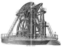
The Cooper Corliss engine served The Matthiesen-Hegeler Zinc Company of Lasalle, Illinois from 1914 to 1965. One of six large engines, it powered a rolling mill and a line shaft that powered other equipment.
In 1981, Fred and Cynthia Carus of Lasalle, Illinois donated the engine to the Stephenson County Antique Engine Club. The club dismantled and moved the engine to Freeport. All labor and trucking were donated. Parts were stored until 1988 when the club acquired the former Stephenson County Nursing Home building, which now houses the museum.
In the yard behind the museum, a foundation was made for the 130-ton engine. Seven vertical holes 25 feet deep by two feet in diameter were drilled in the ground and filled with reinforced concrete to support a base containing nearly 100 yards of concrete and 4000 feet of 1-inch diameter steel reinforcement bars. The total cost was $16,000.
In 1989, the engine was then assembled by club volunteers. The 25-foot, 4-inch flywheel consistes of twelve 5-ton sections connected by 24 bolts, three inches in diameter, and 96 dog-bone shaped keys 2.5 inches square by thirty inches long. It is supported by a 25-ton crankshaft. Assembly of the engine required 12 hours.
In 1990, a 60 by 60 foot metal building was built over the engine at a cost of $30,000.
In 1991, the club located and purchased a used gas-fired boiler and installed it in the building with the engine. The engine was test run on July 13, 1991 at six rotations per minute. It is capable of 45 RPM.
In 1992 the engine was painted. This required 16 gallons of paint.
The engine is the largest flywheel steam engine within 500 miles of Freeport. The flywheel weighs 60 tons and stores a quarter million foot pounds of torque.
There is no admission to see the Cooper Engine. Donations are appreciated.
Corliss Valve Gear
Corliss Engine Group Gear Mechanisms: Corliss steam engine
Corliss Engine Group Gear Mechanisms: Corliss steam engine
A Corliss steam engine (or Corliss engine) is a steam engine, fitted with rotary valves and with variable valve timing patented in 1849, invented by and named after the American engineer George Henry Corliss in Providence, Rhode Island.
Engines fitted with Corliss valve gear offered the best thermal efficiency of any type of stationary steam engine until the refinement of the uniflow steam engine and steam turbine in the 20th century. Corliss engines were generally about 30 percent more fuel efficient than conventional steam engines with fixed cutoff. This increased efficiency made steam power more economical than water power, allowing industrial development away from millponds.
Corliss engines were typically used as stationary engines to provide mechanical power to line shafting in factories and mills and to drive dynamos to generate electricity. Many were quite large, standing many metres tall and developing several hundred horsepower, albeit at low speed, turning massive flywheels weighing several tons at about 100 revolutions per minute. Some of these engines have unusual roles as mechanical legacy systems and because of their relatively high efficiency and low maintenance requirements, some remain in service in early 21st century (see, for example, the engines at the Hook Norton Brewery and the Distillerie Dillon in the list of operational engines).
1 Corliss engine mechanisms
1.1 Corliss valve gear
1.2 Corliss valves
1.3 Barring and barring engines
2 Company history
3 Centennial Engine
4 List of operational engines
5 See also
6 References
7 External links
Corliss engines have four valves for each cylinder, with steam and exhaust valves located at each end. Corliss engines incorporate distinct refinements in both the valves themselves and in the valve gear, that is, the system of linkages that operate the valves.
The use of separate valves for admission and exhaust means that neither the valves nor the steam passages between cylinders and valves need to change temperature during the power and exhaust cycle, and it means that the timing of the admission and exhaust valves can be independently controlled. In contrast, conventional steam engines have a slide valve or piston valve that alternately feeds and exhausts through passages to each end of the cylinder. These passages are exposed to wide temperature swings during engine operation, and there are high temperature gradients within the valve mechanism itself.
Clark (1891) commented that the Corliss gear 'is essentially a combination of elements previously known and used separately, affecting the cylinder and the valve-gear'.The origins of the Corliss gear with regard to previous steam valve gear was traced by Inglis (1868).